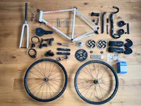
This is a documentation of my Fairlight Strael build process. You might also be interested in my Fairlight Strael Build Notes, which are the primer of this build.
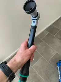
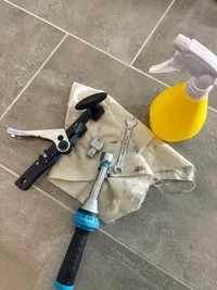
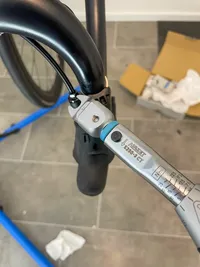
Shimano TL-LR15 Cassette Removal Tool for HG Cassettes and CenterLock Brake Rotors
Steps
Tubes and tires: Because I do not run tubeless I have to remove the tubeless valves first. From that point on I'm following How to change an innertube. Shimano recommends not to use tire leavers with the C36s, and fortunately, the GP5000s didn't require it. Tires are inflated to 60 PSI.
Brake rotors: Once the rim is protected by the inflated tire it's save to mount the brake rotors and torque them to 40 Nm. I do not use anti-seize nor grease for the direct mount connection and the lockring threads of the rotors. The parts are all aluminium and the given torque spec is for dry torque (without grease or anything similar). Putting anti-seize or grease on the thread would increase thread-tension when torquing it to 40 Nm. Generally I avoid using grease near the brakes.
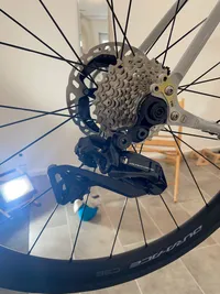
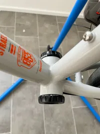
Cassette: Be careful when mounting the cassette. It will fall apart all too easily and you might have difficulties putting everything back in the right order. I put a thin film of anti-seize on the freehub body to help demounting the cassette later on. It could well be that's not necessary because the sprockets are on an aluminium spider and the freehub body is also alumunium. Again, no anti-seize on the lockring thread which will be torqued down to 40 Nm.
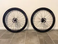
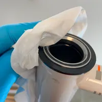
The assembled Dura-Ace C36 wheels, inflated to 60 PSI.
Di2 Wiring
Tools
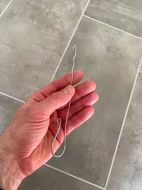
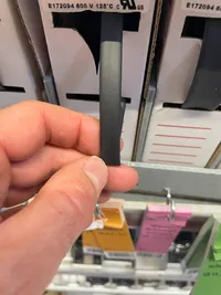
My very high end do-it-yourself routing tool – a short and bent steel wire.My high end Di2 wire routing tool
Folding Meter
Di2 Plug Tool for EW-SD300 wires (TL-EW300)
5 mm Hex Key
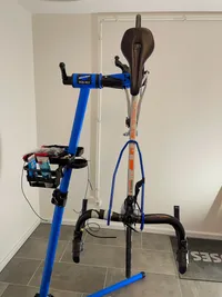
Park Tool Repair Stand PCS-10.3. I'm happy with that. It is sturdy, has a secure and stable stand, can be adjusted in height, and the clamp mechanism works pretty well.
Park Tool Handlebar Holder HBH-2
Tesa Crepe
Electrical Tape
Steps
I use the following process for the wiring: Pushing the Di2 wire through a tube into the desired direction. When the Di2 wire plug becomes visible at the target opening I use my do-it-yourself routing tool to fish the Di2 wire out of the target opening and pull the Di2 wire by hand further. It's not necessary to have anything more.
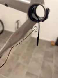
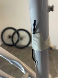
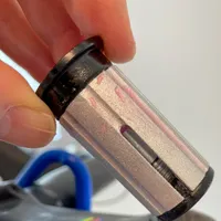
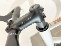
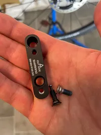
Battery: The wiring starts by inserting the Di2 battery into the seatpost. The Ritchey Battery Mount surrounds the battery nicely and fits well into the Ritchey seat post.Ritchey Battery MountThe battery has to be pushed into the seat post (further than you see on this image)
Seat tube wire: I push a 700 mm Di2 wire into the seat tube from the top opening towards the bottom bracket shell. The wire has three wire holders attached to prevent it from moving inside the seat tube. I use a folding ruler to push the wire towards the bottom bracket shell.
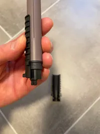
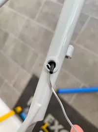
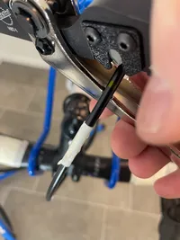
Mounting the seat post: The seat post wire can now be connected to the battery by using the Shimano Plug Tool. As a next step the seat post can be mounted to the frame. Now the frame is ready to be taken into the repair stand by clamping the seat post with the 5 mm Hex Key. The Di2 wire plug has not been pulled out of the seat tube. With the frame inside the repair stand this is left to be done and I use my routing tool to fish the plug and pull it further trhough the bottom bracket shell.Pulling the Di2 plug out of the seat tube into the bottom bracket shell
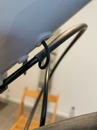
Rear derailleur wire: That didn't went ideal. At first I pushed a 650 mm Di2 wire without any routing tool and with three wire holders attached from the rear lug through the chain stay towards the bottom bracket shell. At some point I couldn't make any progress and because of the wire holders it was pretty difficult to pull the wire back out of the chain stay. I needed to apply so much force that I'm in doubt about the wire integrity. My second attempt was to remove the wire holders except of one, and push the wire, starting at the bottom bracket shell, through the chain stay to the lug at the end of the chain stay. When the wire plug became visible through the lug it was again time for my DIY routing tool to fish the Di2 wire through the lug.Fishing the Di2 wire with my routing tool
That second attempt went smoothly. The one wire holder that was attached to the Di2 wire was near the bottom bracket shell. By pulling the Di2 wire further through the chain stay in direction of the dropous, the wire holder slipped into the chain stay. Then I added another wire holder near the dropouts and pulled the Di2 wire back a little bit into the direction of the bottom bracket shell. As a result I have two wire holders attached to the Di2 wire. Because of my concerns about the Di2 wire integrity I repeated the process with a 700 mm wire (that is a leftover wire and 700 mm seem to be the better choice anyway).
Down tube wire: After removing the Fairlight cable guide from the down tube the lug appears to push the 1200 mm Di2 wire through. I remove all wire holders and route the wire through the down tube towards the bottom bracket shell. With my routing tool, again, I can fish the plug out of the tube opening inside of the bottom bracket shell and pull the wire further so that finally 60 cm of wire hang out of the bottom bracket shell. Now I can attach four wire holders and pull the wire back into the down tube. Very smooth.
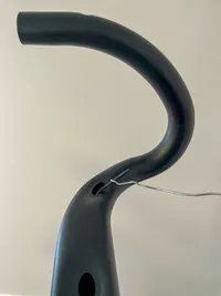
Handlebar wire: It's easy to push the 700 mm Di2 wire through the handlebars and fish the wire plug with my routing tool out of the lug. I've 4 wire holders attached.Fishing the Di2 wire plug out of the handlebar lug opening
Front derailleur wire: This is a 300 mm Di2 wire. I insert it through the lug in the down tube with a single wire holder attached. Again I use my DIY routing tool to get the wire out of the down tube into the bottom bracket shell.
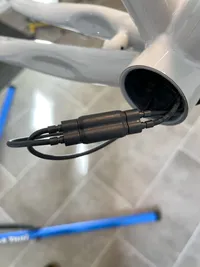
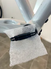
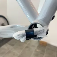
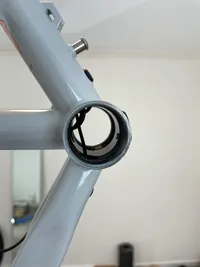
Junction: All the wires ending in the bottom bracket shell are getting connected with the EW-JC304 junction. Then I'm wrapping the junction into left over packaging material to provide some padding and avoid rattling. The packaging material is fixated with electrical tape.The EW-JC304 junction with all four wires plugged inRecycling of packaging materialI'm wrapping the junction into the packaging so that the plugs are also coveredFixating the packaging with electrical tapeThe Di2 wires tucked away in the bottom bracket shell. The EW-JC304 junction is wrapped with the packaging and pushed into the down tube.
All dangling Di2 wires are fixated with Tesa Crepe. The wires are only plugged into the EW-JC304 junction and not into any of the Dura-Components.The Di2 dangling wire fixation
Determine the desired stem height
Tools
Pencil
Folding Meter
Water Level
4 mm Hex Key
5 mm Hex Key
6 mm Hex Key
Steps
Before cutting the steerer tube I assemble the fork into the frame and put as many spacers onto the steerer tube as I assume will be needed. I have the geometry of the new frame and can compare it to the geo of my old frame. Theoretically I can calculate the number of required spacers but cutting off something from my shiny new fork scares me in a way that I want to try things first. That in addition requires mounting the handlebars, the shifters, the wheels and the saddle.
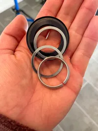
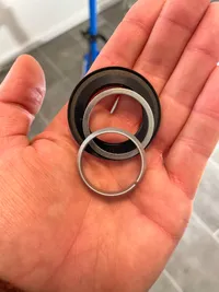
Fork: The headset top cap comes with two shims. I found to get a tight outer seal for the rubber of the headset top cap one spacer was enough in my case. The Hope headset has three convincing seals (two top, one bottom).
The headset comes with two optional shimsRemoving one of the shims to get a tight seal
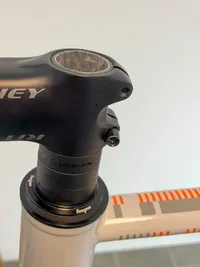
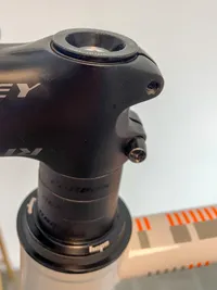
After putting the fork into the head tube, I'm mounting the headset and putting 3 x 1 cm spacers onto the steerer to lift the stem. I do not apply any grease at this point in time because everything will be disassembled again to cut the steerer tube. The stem is not fully tightened for now.
Lifting the stem by 3 cm
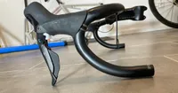
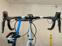
Handlebars with shifters: Please refer to the Shimano Dealer Manual for Hydraulic Disc Brake R9250 to see how you can mount the shifters to the handlebars. I adjust the shifters like you see in the image. This way the brake lever has just the right distance to the drop bar hand position and the shifter hoods prolonge a straight top line for the upper handle bar.Finding a shifter position
I adjust the side rotation of the shifters by aligning a water level with the side of the handlebars and making shure the shifter level touches the edge of the water level ever so slightly.
Adjusting the side rotation of the shifers
Once the shifters are in tune, I'm mounting the handlebars to the stem, center the handlebars, and tighten the stem to the steerer a little bit more, but not to the final torque.
Wheels: The thru axles of the Strael require a 6 mm Hex key for mounting the wheels.
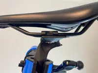
Saddle: The saddle is mounted with a 5 mm Hex Key and put to the correct height, measuring from the center of the bottom bracket shell to the main sitting area. I've read that the Ritchey Link seat post makes it difficult to tune in the right saddle position but I found it quite the opposite. It's a clear, simple, and straightforward interface and I couldn't ask for more.The Ritchey Link seatpost clamp works pretty fine
Cut the steerer tube
Tools
Tesa Crepe
Hacksaw with Park Tool Carbon Cutting Saw Blade CSB-1. You do not need the Park Tool saw itself if you already have a hacksaw that can hold the 300 mm saw blade.
Topeak Threadless Saw Guide
Sanding Block with P120 Sanding Paper
FFP2 Mask
Nitril Gloves
Steps
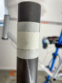
I'm following How To Cut A Road Bike Steerer Tube as presented by the Global Cycling Network. After trying out the desired stem height I draw a line with a pencil around the 5 mm spacer that sits on top of the stem. Then I take away the wheels and disassemble the fork from the bike frame.
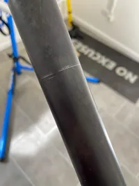
For the compression bung to work properly I have to cut away 3 mm in addition. Make sure it's exactly 3 mm because cutting only additional 2 mm is too less and will lead to the compression bung not function. If you cut 2 mm initially you can imagine it's difficult to cut another 1 mm. I know what I'm talking about because that's exactly what happened to me.On this image you see three lines on the steerer. From top to bottom:
A thin line going aroung the steerer. That was my first line before noticing that I should take away one of the headset shims for a tighter seal.
A thicker line going around the steerer. That is the top height of the final 5 mm spacer that sits on top of the stem.
A very short line. That is the cut mark that must be 3 mm below the top spacer height but was only 2 mm in my case – which was not enough.
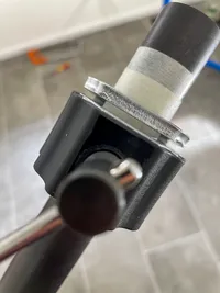
I put a very short Tesa tape to mask the cut line. Above and and overlapping the short tape comes another Tesa around the entire steerer to improve the cut.The two Tesa tapes on top of each other and an additional pencil line to identify the cut mark easily
The saw blade guide can be attached to the steerer just so that cut will go through the identified cut line.The saw blade guide attached to the steerer
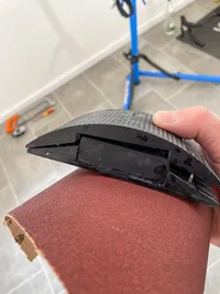
It's time to cut the steerer with the hacksaw. I've attached the Park Tool Carbon Blade to my plain old 300 mm hacksaw for the cutting. I'm wearing an FFP2 mask (easy to have one at hand during a pandemic) and I should have worn Nitril gloves (which I didn't do). Because I do not own a vice I'm sitting down, laying the fork on my knees and do the sawing. Admittedly, it would be better to mount the sawing guide into a vice for this job. After the cut is made, I do some gentle sandpaper grinding of the cutting area. I use a sanding block and P120 sandpaper. Finally I remove the Tesa tape from the steerer.The sanding block with the P120 sanding papier
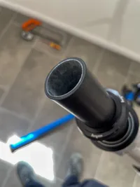
The result is an even and smooth steerer cut.The smoothened steerer cut
Mount the fork to the frame
Tools
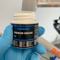
Shimano Premium Grease
Nitril Gloves
Carbon Fitting Paste (came with the Strael frame)
4 mm Hex Key
5 mm Hex Key
6 mm Hex Key
Hazet 5280-3CT Torque Wrench
Steps
I'm applying a thin layer of grease to the headset top cup. The upper bearing will be placed inside the greased cup. It's only a thin layer because too much grease would attract dirt and the Hope headset is nicely sealed with two rubbers therefore I think not much grease is required to protect the headset – I use it only as an anti corrosive and to simplify getting the bearing out of the top cup if maintenance would be required. The bearing itself is a greased cartridge bearing that doesn't require any additional grease.The Shimano grease I'm using. You don't need much of it.Applying grease to the tup cup
Installing the bearing into the prepared top cup. Be careful to do it the inner cone pointing top and the outer cone pointing to the bottom.The bearing goes into the prepared top cup with the outer cone pointing to the bottom.The top bearing inserted into the top cup
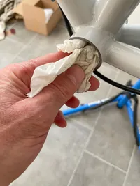
Wiping away excess grease from the top cup but not from the top bearing.I'm wiping away any excess grease carefully
The headset bottom cup will also receive a thin layer of grease, similar to the top cup.
With the bottom bearing onto the fork steerer tube I insert the fork into the frame and slide the coned ring, the top cup shim, and the headseat top cap over the steerer tube. After the fork is inserted into the head tube, the coned ring, the top cup shim, and the headset top cap go from bottom to top order onto the steerer
The headset top cap sits so tight that the fork will stay in the frame. Finally I'm attaching the three stem spacers, followed by the stem.
The fork with all top spacers and stem
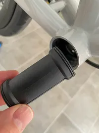
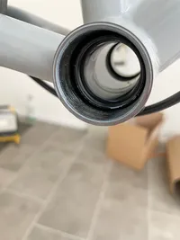
The compression bung receives a thin layer of carbon fitting paste and is installed into the steerer tube. I apply 6 Nm torque.The compression bung with carbon fitting paste appliedThe installed compression bung torqued to 6 Nm
Attach the top cap to the steerer with a final 5 mm spacer and torque the top cap screw hand tight to preload the headset bearings.The attached top cap
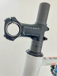
I attach the wheels to take the frame out of the repair stand and straighten the steering unit. Every headset screw receives 4 Nm of torque, except the steerer top cap wich remains hand tight. Ritchey allows a maximum torque of 5 Nm for their 4-bolt-stems, see Ritchey Tech Info. The result starts looking like a bike.
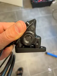
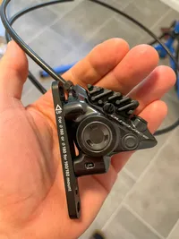
I connect the Flat-Mount adapter (SM-MA-R160D) to the rear caliper and use the caliper fixing screws (Type B) that are supplied with the adapter. Torque is 6 Nm. Then I attach the screw fixing pin that came with the caliper by pushing it completely into the caliper until it is fully inserted.
The Flat Mount Adapter (SM-MA-R160D) with Type B caliper fixing screws that came with the adapterThe rear caliper with the attached Flat-Mount adapter. The screw fixing pin is not yet installed.
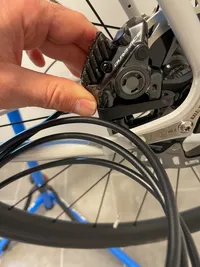
I mount the rear caliper to the frame.
Attaching the rear caliper to the frame
The Strael comes with two Type A screws for a 15 mm frame that can be used but I use one Type A and another Type C. Do not forget the two distance washers that came with the adapter, otherwise you will damage the caliper. I do not tighten the bolts because later the caliper will get adjusted to the brake rotor. The retaining clip can still be attached to the Type C screw.
The Type A and Type C screw with retaining clip and distance washers
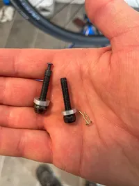
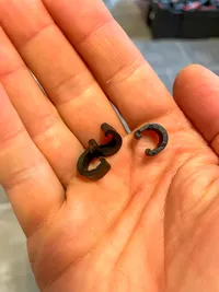
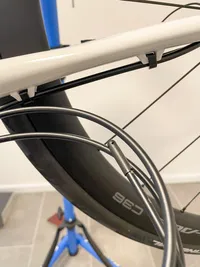
I route the brake hose along the frame and fixate it with the C-Clips.
C-Clips
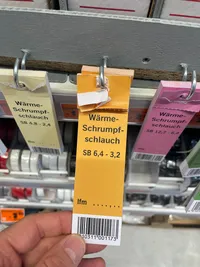
From the upper end of the down tube I push the Di2 wire completely through a 50 cm long shrink tube. It's important to begin with the Di2 wire first and not with the brake hose!
Then I push the brake hose through the shrink tube. The shrink tube has a diameter of 6.4 mm → 3.2 mm. It's not required to shrink the tube and keep the 6.4 mm in diameter. If you leave it like that it will just look fine in my view.
The shrink tube I'm using – I get it from the construction marketThe Di2 wire and the brake hose pushed through the shrink tubeRouting Di2 wire and brake hose from the down tube to the handlebars
I fixate the shrink tube that contains the brake hose and the Di2 wire to the handlebars with Tesa Crepe. I'm not cutting the brake hose yet and I do not connect the brake hose to the shifter because I first want a proof Di2 is working properly.
Install the front caliper
It's straightforward to attach the caliper to the fork because it comes pre-installed with an adapter for 160 mm rotors.The front caliper with adapter for 160 mm rotors
I attach the caliper to the fork but I do not tighten the Type A screws that come with the caliper because later the caliper will get adjusted to the rotor.Installing the front caliper
The brake hose can easily get pushed through the fork up to the handlebars.Pushing the brake hose through the fork
I fixate the brake hose with Tesa Crepe at the handlebars in the desired position. The brake hose is not cut yet and not connected to the shifter.The brake hoses are put into position
Install the derailleurs and complete the wiring
Heads Up: For the Di2 wire connection of the two Dual Control Shifters it's crucial to use the lower satellite ports of the shifters! The connection from one shifter to the junction in the down tube (in my case it's the right shifter) must go through the upper port of the shifter. If you do not follow this wiring model your shifter firmware updates and the triggering of the derailleurs through the shifters will not function properly!
Also make sure to use blind plugs for the ports you don't use.
Tools
Hazet 5280-3CT Torque Wrench
Di2 Plug Tool for EW-SD300 wires (TL-EW300)
5 mm Hex Key
2 mm Hex Key
Rear derailleur
Follow the Rear Derailleur (Di2) Dealer Manual R9250 step by step to install the rear derailleur (standard type) and connect the Di2 wire with the derailleur. The rubber cover and the cable guide for the wire are part of the derailleur packaging.
Mounting the rear derailleur (standard type) with a max torque of 8 - 10 NmThe B-tension stop of the rear derailleurThe rear derailleur attached to the frame
Front derailleur
Follow the Front Derailleur (Di2) Dealer Manual R9250 step by step to temporarily install the front derailleur with a band adapter to the frame and connect the Di2 wire with the derailleur. The plug cover for the Di2 wire is part of the derailleur packaging.
The final position of the front derailleur cannot be set at this point because the crankset is not installed yet. Attach the band adapter somewhere in the middle of the two bottle cage screws to the seat tube. The final positioning will be done after proper operation of the electronic shifters is verified and the crankset is installed.
Dual Control Shifters
Connect the two shifters with each other with the wire that's routed through the handlebars. Use the lower satellite ports of the two shifters!
Then connect the wire dangling out of the down tube with the right shifter by plugging it into the upper E-Tube port of the right shifter.
Charge the battery with an USB AC charging adapter. The battery will be charged after 1.5 to 2 hours. Refer to the Rear Derailleur (Di2) and Battery Charger handbook.
Verify Di2
With all Di2 wires connected and the battery charged the Di2 system is ready to be paired. As described in Rear Derailleur (Di2) Dealer Manual R9250 under System pairing (wired) this is done by pressing and holding the function button of the rear derailleur until the LED changes from yellow to flashing blue (5 - 8 seconds). The LED flashes green if system pairing succeeds, or flashes red if pairing fails.
After pairing, signals sent from the shifters to the derailleurs should be functioning. Try the shift switches of the two shifters and verify the derailleurs are moving each in their both shifting directions.
Download and install the E-Tube Project App onto your phone. The app will be necessary later to make gear shifting adjustments and to install software updates into the gearing system.
Press the function button of the rear derailleur until the LED flashes blue (0.5 - 2 seconds). The bicycle side is ready to connect. The unit name is displayed on the E-TUBE PROJECT screen.
Start the E-Tube App (Bluetooth must be activated on the phone).
Select the unit name displayed on screen. Follow the E-Tube Project Cyclist manual to set up the app and create an entry for the bike for the first time.
Install the bottom bracket
Tools
Wera Click-Torque X 3 Torque Wrench
24 mm Hex Socket for the Torque Wrench
Pedro's Bottom Bracket Socket for 16-notch x 44mm External Bearing BB Cups and Disc Brake Lockrings
Isopropyl Alcohol
Anti-seize
Paper Towel
Steps
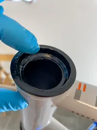
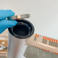
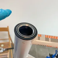
Clean the bottom bracket shell with a paper and isopropyl alcohol.Preparing the bottom bracket shell with isopropyl alcohol
Tuck away the Di2 wires and push the plastic cover of the Rotor BB1 bottom bracket into the bottom bracket shell. Be careful with the Di2 wires. My first attempt was to install the Shimano Dura-Ace Bottom Bracket but the plastic cover that would shield the axle is a millimeter too wide in diameter which made it impossible for me to get it past the Di2 wires into its place. The Rotor BB1 plastic cover is ever so slightly smaller and therefore works just fine.Insert the Rotor BB1 plastic coverThe inserted Rotor BB1 plastic cover. The Di2 wires go around that cover.
Prepare the BB1 cups with anti seize and screw them in. I tighten them to 40 Nm with the Wera Torque Wrench.A BB1 Cup prepared to be screwed into the bottom bracket shellThe two cups screwed into the BB shellThe Wera X Torque is ready to tighten the bottom bracket cups to 40 Nm
Assemble and install the crankset
Tools
10 mm Hex Key
2.5 mm Hex Key
Anti-seize
Wera Click-Torque X 3 Torque Wrench
Steps
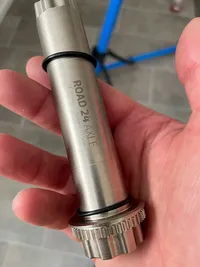
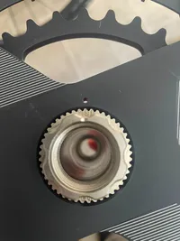
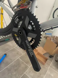
Assemble Rotor ALDHU drive-side crankarm with the chainring and the axle. The video ALDHU crankset assembly with Q RINGS® Direct Mount Chainrings will give an impression about the assembly of the crankset. First I mount the 32-48 chainring to the axle by center-aligning the axle imprint "531" with the tiny chainring hole (I think the tiny hole is called OCP indicator – for Optimum Chainring Position).The Rotor 24 mm Road Crank Axle. Mind the two O-Rings: the drive-side O-Ring is thinner than the non-drive-side O-Ring. The Rotor axle comes with additional spacers but none of them is needed for the installation to the Strael.The NoQ chainring centered on the axle
The chainring is kept in place by mounting the drive-side crank arm on top of it. The crankarm must be centered above the metal pin sticking out the outer chainring and should be tightened with a 10 mm hex key to 35 - 40 Nm. In my case 35 Nm was not enough because the chainring then was sitting wobbly on the axle. Once tightened to 40 Nm the parts were without any play. I use anti-seize on the crankarm thread before screwing it into the axle.
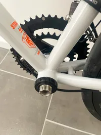
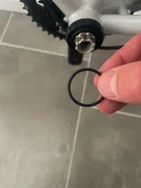
Before pushing the axle through the bottom bracket take away the non-drive-side O-Ring from the axle and push the drive-side O-Ring as far as possible on the axle into the direction of the chainrings. Then push the axle completely through the bottom bracket (you might apply gentle force) and reattach the non-drive-side O-Ring to the axle.The drive-side of the crankset. The front derailleur is not in its final position.The non-drive-side. On the picture the crank axle is not fully pushed through the bottom bracket – it can be pushed around one centimeter further but I did not recognize that when taking the picture.Do not forget to reattach the non-drive-side O-Ring to the axle
Loosen the preload nut bolt of the non-drive-side crankarm with the 2.5 mm hex key and thread the preload nut clock-wise into the crankarm until it bottoms out.
Mount the non-drive-side crankarm to the axle with a 10 mm hey key and torque it to 40 Nm. I use anti-seize before screwing the crankarm onto the axle.
Screw the preload nut anti-clock-wise and hand-tighten it until there is no play in the crank/axle/bottom bracket system. Tighten the preload nut bolt to 1 Nm (not much!).
Mount the pedals
Tools
8 mm Hex Key
Hazet 5280-3CT Torque Wrench
Steps
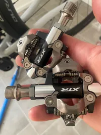
There is not much. I use anti-seize on the pedal threads and screw them into the crankarms. I'm aware the pedals should be torqued to 30 - 40 Nm generally but I torque it to 15 Nm which is already so tight that loosen it later is sometimes difficult.
The pedals I'm using on all of my bikes
Install the chain
Tools
TOPEAK All Speeds Chain Tool
Radon Foldable Chain Holder
Quick Link Chain Lock Tool
Steps
Determine the chain length by following the Rear Derailleur (Di2) Dealer Manual. Please read the chapters Installing the chain and Checking the chain length under Adjustment. It's basically wrapping the chain around the largest sprocket as well as the largest chainring to identify the zero point. Then adding two or three links plus the Quick-Link to the zero point.
Shorten the chain with the TOPEAK Chain Tool.
Position the front derailleur so that the chain can get routed without rubbing through the the derailleur cage. This is still a temporary positioning – the final position is set when the gear shifting will be adjusted.
Only now route the chain through the front derailleur and through the rear derailleur, take care of the chain direction, and link it with the Quick Link chain lock. The Foldable Chain Holder as well as the Quick Link Chain Tool simplify installing the Quick Link.
Adjust gear shifting
Tools
Shimano GG Adjustment Gauge to set the B-screw of the Rear Derailleur, this will come packaged with the derailleur
Phone with E-Tube Project App installed
2 mm Hex Key
5 mm Hex Key
Hazet 5280-3CT Torque Wrench
Steps
Set the final position of the front derailleur by following the chapters Installation/Removal and Securing of the Front Derailleur (Di2) Dealer Manual R9250. Torque the fixing screw to 5 Nm and screw in the support screw. Torque the clamp screw also to 5 Nm.
I do the adjustment of the high limit and the low limit of the front derailleur with the E-Tube Project App on my phone in a later step. The front derailleur doesn't have limit bolts!
Set the high and low limits of the front derailleur with the E-Tube Project App. The bike needs to be in a repair stand so that you can rotate the cranks by hand. Connect the E-Tube Project App on your phone with the rear derailleur. Start the E-Tube App (Bluetooth must be activated on the phone). Press the function button of the rear derailleur until the LED flashes blue (0.5 - 2 seconds). The bicycle is ready to connect. Select the unit name displayed on screen.
Open the Maintenance tab and under Derailleur adjustment select Front and follow the instructions of the app.
Cut the brake hoses
When cutting a brake hose it is essential to have all tools and materials available and prepared upfront. You don't want to search for a tool while holding a cut-off brake hose filled up with mineral oil in your hand!
The Shimano Dealer Manual for Hydraulic Disc Brake R9250 explains how to cut and install the brake hoses. The Shimano Brake Hose Easy Joint system, which you will use when the calipers come pre-bled and with the hose installed, is a breeze to set up. Because of the Easy Joint system you probably do not need to bleed the brakes after your brake hoses are installed.
Tools
4 mm Hex Key
8 mm Wrench
Hazet 5280-3CT Torque Wrench with 8 mm Torque Wrench Insert{}
Park Tool HBT-1 Hydraulic Barb Tool
Isopropyl Alcohol
Cleaning Paper
Connector Insert for the Brake Hose (SM-BH90-JK-SSR)
My prepared tools for cutting the brake hoses. See the tiny connector insert in the middle of the arrangement.
Steps
Repeat the steps for each brake hose.
Measure the desired length of the brake hoses. The hose will be inserted 21 mm into the connector port of the lever - consider that and make two marks on the hose: one where to cut and another witness mark 21 mm behind the cut mark. I do it so that there is some slack around the handlebars and at the same time the hoses are not rubbing each other or a part of the bike.The bike prepared for measuring
Put the bike within the repair stand into a position so that the hose connectors of the the shifters (the ones with the yellow plugs inside) are pointing upwards.The hose connectors of the shifters are pointing upwards
Pull the hose seal plug out of the brake hose connector.
Cut off the brake hose with the Hydraulic Barb Tool.The cutting of the brake hose with the ParkTool HBT-1. The witness mark is the Tesa Crepe while the cut mark is difficult to see (but still there).
Use the Hydraulic Barb Tool to press the connector insert into the brake hose.
The shifter comes with a pre-installed olive. Push the cut-off brake hose into the brake hose connector port of the shifter until it bottoms out (the witness mark should now be aligned with the outer casing of the hose connector). Wrap a paper towel around the connector port while doing this.
Tighten the flare nut – first with the 8 mm wrench and then with the torque wrench to 5 Nm – while pushing the hose into the connector port.Torque the flare nut to 5 Nm
Wipe away any excess oil with Isopropyl alcohol and a paper towel.Wipe away excess oil
Do not forget: Take away the lever stopper and align the caliper with the brake rotor by loosening the caliper fixing screws, pulling the brake lever and then torqueing the caliper fixing screws to 6 Nm. The front caliper will then get a snap ring installed while the rear calipers gets a screw fixing pin. Look that up in the Shimano Dealer Manual for Hydraulic Disc Brake R9250.
Wrap the handlebars
Tools
Scissors
Electrical Tape
Steps
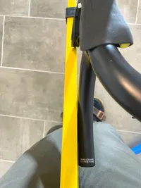
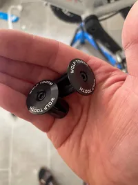
I'm following How to Wrap Handlebars for Road Bikes. Because I'm using Pro Race Comfort Bartape with an adhesive silicone strip rewrapping to get the perfect result is no issue. The tape could be a little bit longer. Unfortunately I cannot install the Wolf Tooth Bar End Plugs because they do not stay in place which might be because the bartape is a bit thicker. The plugs that come with the Pro Race Comfort bartape are working fine instead.
Unfortunately the Wolf Tooth Bar End Plugs do not stay in place and I cannot use them
Shimano TL-LR15 Cassette Removal Tool for HG Cassettes and CenterLock Brake Rotors
My very high end do-it-yourself routing tool – a short and bent steel wire
Folding Meter
Di2 Plug Tool for EW-SD300 wires (TL-EW300)
5 mm Hex Key
Park Tool Repair Stand PCS-10.3
Park Tool Handlebar Holder HBH-2
Tesa Crepe
Electrical Tape
Pencil
Water Level
4 mm Hex Key
6 mm Hex Key
Hacksaw with Park Tool Carbon Cutting Saw Blade CSB-1. You do not need the Park Tool saw itself if you already have a hacksaw that can hold the 300 mm saw blade.
Pedro's Bottom Bracket Socket for 16-notch x 44mm External Bearing BB Cups and Disc Brake Lockrings
10 mm Hex Key
2.5 mm Hex Key
8 mm Hex Key
TOPEAK All Speeds Chain Tool
Radon Foldable Chain Holder
Quick Link Chain Lock Tool
Shimano GG Adjustment Gauge to set the B-screw of the Rear Derailleur
Phone with E-Tube Project App installed
8 mm Wrench
Park Tool HBT-1 Hydraulic Barb Tool
Isopropyl Alcohol
Cleaning Paper
Torque table
Note on Apr. 20, 2025
Fairlight now has page with torque settings for their bikes. In case they recommend something different than what I've used, their value is now added to the last column of the below table.
Component
Torque I used in Nm
Max allowed Torque in Nm
Fairlight
Bottom Bracket Cups
40
45
Brake Rotor Centerlock
40
Calipers to the fork or frame
6
max 6 - 8
Cassette to freehub body
40
Compression bung
6
max 10
10
Dual Control Lever clamp screw
5
max 6 - 8
Flare nut to fix hydraulic hose with shifter
5
max 5 - 6
Front derailleur clamp screw to mount the clamp to the frame
5
max 5 - 7
5 - 6
Front derailleur fixing screw to attach the derailleur to the clamp band