Writing software is comparable to the work of an author writing a book. Of course, there are engineering elements and creative and social aspects that characterize the work of a software developer, but the contemplative articulation of a model into code is authoring to me. The better we can communicate the underlying model, the better the system can grow. Indeed the ability of the system to develop is coupled to our shared mental model about the system.
Often a model is communicated by using graphical- or diagram techniques. But no single diagram type covers all aspects of a software system model. Instead, we use different pictures to explain and communicate various issues of the system. The Unified Modeling Language (UML) is a standardized language that reflects this fact by providing many different diagram types, which are grouped into the structure- and behavior diagrams.
In case you are a business domain expert, software developer, requirements engineer, tester or architect – do you know your UML diagram types?
UML diagrams have their value, but only if the ones who work with them have a shared understanding of how to read and write this language. If specialists only use the charts for special meanings and sometimes just being created and consumed by the same single author, they do not foster communication among different members (with different skills) of a software development project but instead, have the opposite effect, because
- they are not understood well enough or
- they are not up to date because their creation is too time-consuming or
- the software to maintain and read the diagrams is not available to all project members.
Therefore the usage of the UML diagrams should be decided with care and insight.
The here proposed Box-Bullet-Line notation is an easy to use drop-in, that allows to
- model data flow
- see components and their dependencies
- indicate callers
- have calling sequences
- use synchronous and asynchronous communication patterns
- still be able to draw easily by hand.
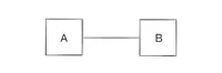
Dependency
Let's start with the basics. A line between two boxes indicates a dependency between two system components. A box is a component. In early phases, when you explore an existing system or design a new one when directions of communication are not of highest importance, the undirected dependency between components is a good starting point.
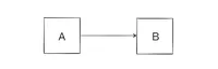
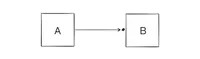
Flow
The directed connection from A to B has the meaning of „data flow from A to B“.
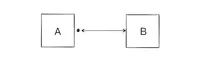
Caller
The caller can be marked with a tiny bullet.
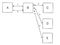
Sequences
By using numbers beside the connections, calling sequences can be modeled.
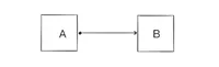
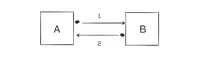
Synchronous and asynchronous
Synchronous and asynchronous communication can be modeled with single and doubled connections.
This simple Box-Bullet-Line notation can grow with your needs. For example, you can start modeling only undirected connections, add data flow by giving your relationships a direction and extend even more by adding caller indication with calling sequences later. You can also use a swim-lane structure and place the components into those lanes, to communicate tags or domains that the components belong to.